With more and more HF amateurs becoming increasingly concerned with bandwidth, the station monitor solutions model RF-D
(RF Demodulator), series RF-S (Variable RF Sampler), Splatter View and series RF-AM
(AM Modulation Monitor) were created to insure that your signal remains truly distortion free and linear. Providing a real time reference
observation of your signal is now possible, eliminating the true root causes of splatter, buckshot, over/under modulation and nonlinearity!
The possibility of your 3rd and 5th order IMD (Inter-Modulation Distortion) products will be exponentially reduced;
assuring that your occupied bandwidth will be directly proportional to your transmitter's audio passband, not a mistuned nonlinear amplifier
or transmitter.
All oscilloscopes represent a given voltage displayed visually near the speed of light in real time, with no mechanical
lag. This idea, incorporated with RF station monitoring solutions provided by the model RF-D, series RF-S,
and RF-AM produces great details about your RF signal that a mere wattmeter would never be able to display!
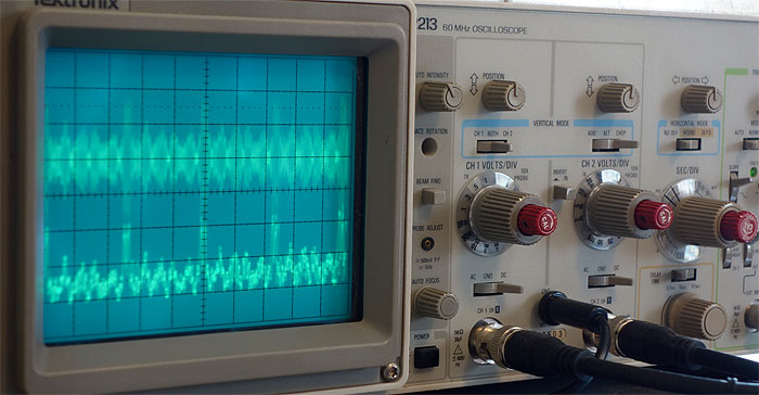
Note 1:Your oscilloscope's ability to measure RF will be limited by the vertical
amplifier's maximum bandwidth. A 30 MHz oscilloscope or higher is therefore recommended to easily cover the entire HF radio frequency spectrum.
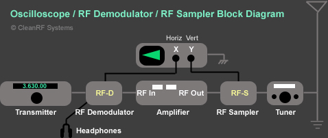
Step 1 (For the RF-D, RF-S Series & Splatter View Series only) - Making the
Connections
!!!WARNING: THE MODEL RF-D (RF DEMODULATOR) MUST BE CONNECTED TO THE TRANSMITTER'S
OUTPUT - NEVER TO THE AMPLIFIER'S OUTPUT. FAILURE TO COMPLY WILL DESTROY THE DEMODULATOR AND VOID YOUR WARRANTY!!!
Connect the model RF-D (RF Demodulator)
directly to the output of the transmitter, via the UHF male-to-male connector provided.(Choose either
SO-239 connector since they are bi-directional)
Connect the series RF-S (Variable RF
Sampler) directly to the output of the amplifier, via the UHF male-to-male connector provided. (Choose either SO-239 connector since
they are bi-directional)
Connect one BNC end of your 6’ jumper cable to the BNC connector on the model RF-D
(RF Demodulator) and the other end to the BNC Horizontal "X" input of your oscilloscope.
Connect one BNC end of your 6’ jumper cable to the BNC connector on the series RF-S
(Variable RF Sampler) and the other end to the BNC Vertical "Y" input of your oscilloscope.
See the wiring illustration "Figure 1a" below.
Figure 1a
(1/4" TRS stereo plug required for line out application)
Note 2:The RF Demodulator's 1/4" TRS jack may be used as an AM audio modulation monitor!
Use only with stereo headphones of 63 ohms impedance or greater, stereo line-level unbalanced input to your mixer, or stereo amplifier.
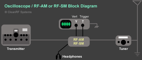
Step 1 (For the RF-AM and RF-SM only) - Making the Connections
To interface the series RF-AM or model
RF-SM after the exciter, use the high quality UHF male-to-male connector and shielded
jumper cables provided. (Choose either SO-239 connector since they are bi-directional)
Connect one of the BNC ends of your 6’ jumper cable to the BNC connector on the
series RF-AM or model RF-SM Variable
RF Sampler out and the other end to the Horizontal CH 2 (Y) input of your oscilloscope.
Connect one of the BNC ends of your 6’ jumper cable to the BNC connector on the
series RF-AM or model RF-SM External
Trigger out and the other end to the External Trigger input of your oscilloscope.
Note: If your oscilloscope does not have an EXT BNC Trigger input (like
the Tektronix 2464B)
substitute the External Trigger for Channel 1 X input. (Click
here to see a photo example...)
See the wiring illustration "Figure 1b" below.
Figure 1b
(1/4" TRS stereo plug required for line out application)
Note 2:The RF Demodulator's 1/4" TRS jack may be used as an AM audio modulation monitor!
Use only with stereo headphones of 63 ohms impedance or greater, stereo line-level unbalanced input to your mixer, or stereo amplifier.
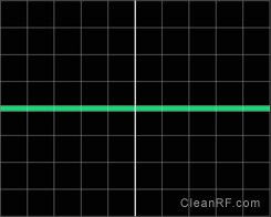
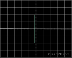
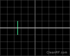
Next, find the controls on your oscilloscope labeled "Position" for both the Horizontal CH 1 (X) and
Vertical CH 2 (Y) axis. Adjust the Position controls so the horizontal sweep trace is centered vertically. Next, find the Horizontal Mode
Position control. Adjust the Horizontal Position control so that the horizontal sweep trace is centered horizontally.
Focusing may be required. We will refer to this as establishing your "Base Line".
See "Figure 2" below.
Figure 2
Establishing Initial Baseline Adjustment
Now, set your oscilloscope's controls for the following:
Horizontal CH 1 (X) voltage scale: 2 Volts / Div for starters
Vertical CH 2 (Y) voltage scale: 2 Volts / Div for starters
Horizontal Mode or display selector to position "A", NO DLY or NONE
Vertical Mode selector to CH 2 and "ALT" (or both if applicable)
Set both Horizontal CH 1 (X) and Vertical CH 2 (Y) channel three way position coupling selectors to "DC"
(Located under the voltage selector knob)
Step 1 - Setting Oscilloscope for Envelope Monitoring:
Turn time or seconds / division sweep control for 1mS for starters.
Turn Trigger sweep mode to Auto, or Normal. (In the Normal mode, the horizontal envelope trace
will turn off when no modulation is present)
Set “A” Trigger coupling to "DC" (if applicable).
If using the Splatter View, select “A” Trigger source to "INT"
or "CH 1" (or both if applicable).
If using the RF-SM or RF-AMseries, select
"A" Trigger source to "EXT".
Note: If your oscilloscope does not have an EXT BNC Trigger input (like the
Tektronix 2464B)
substitute the External Trigger for Channel 1 X input. (Click
here to see a photo example...)
You may need to adjust your "Slope Tune or Level" + or - knob to lock the trigger during
modulation. The Trigger LED indicator will flash during modulation when level is set correctly.
An added advantage of using the trigger selection is the ability to synchronize your horizontal modulation envelope
sweep, regardless of changing voice or data modulated frequencies, in either SSB or AM envelope monitoring.
Step 2 - Calibrating Oscilloscope and Power Output for Envelope Mode:
Tune up your exciter (transmitter) if necessary, and then your amplifier to its rated output
within legal limit operation (1500w PEP). (The linearity tests discussed later in "Application 3" will determine if
you tuned your amplifier properly)
With a continuous carrier established at the desired power level, adjust Vertical CH 2 (Y)
voltage scale control on your oscilloscope so that the centered horizontal sweep trace expands 2 divisions above and below the baseline
established in "Figure 2" on the oscilloscope's display. You should be able to make this adjustment within 10 seconds.
Calibration is now complete and you can proceed to the mode you will be using (SSB or AM).
See "Figure 3" below.
Figure 3
Oscilloscope Calibrated for Full Carrier Power Used
SSB Modulation Envelope Patterns:
When using the SSB or AM modes, adjust your audio gain so that your RF envelope peaks expand
to the established plus and minus 2 divisions previously calibrated for as shown in "Figure 3". A well-modulated SSB modulation
envelope will look like "Figure 4" and an overmodulated SSB pattern is also represented in "Figure 5",
both shown below.
Figure 4
Proper SSB Voice Envelope Pattern at Full Modulation / Drive Power
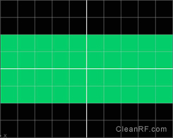
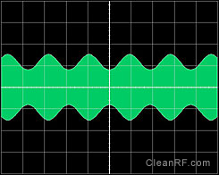
When using AM, first calibrate an unmodulated carrier to the plus and minus 1 division level
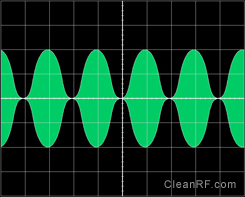
shown in "Figure 6". To achieve a fully 100% modulated envelope, adjust your audio gain so that the envelopes expand 2
divisions above and below the baseline. See "Figure 8" below. This would indicate full PEP modulation at 4 times the unmodulated
carrier level. See "Figures 6, 7, 8, 9a and 9b" below.
Figure 6 Unmodulated AM Carrier Calibration
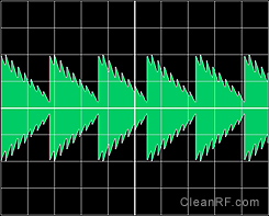
Figure 7
Undermodulated AM Envelope
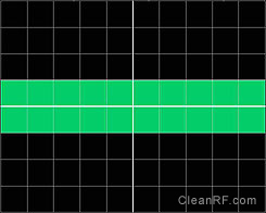
Figure 8
100% Modulated AM Envelope
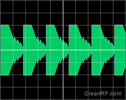
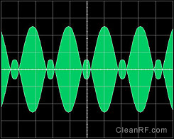
Figure 9a
Overmodulated "Low-Level" AM Envelope (Balanced Modulator)
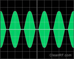
Figure 9b
Overmodulated "High-Level" AM Envelope (Plate Modulation)
"Splatter View" Trapezoidal Pattern Linearity Signal Monitor - System
Self Diagnostic Test:
!!!WARNING: THE MODEL RF-D (RF DEMODULATOR) MUST BE CONNECTED TO THE TRANSMITTER'S
OUTPUT - NEVER TO THE AMPLIFIER'S OUTPUT. FAILURE TO COMPLY WILL DESTROY THE DEMODULATOR AND VOID YOUR WARRANTY!!!
With this method, two detection sources will be used to feed both the Horizontal CH 1 (X) and Vertical CH 2 (Y) inputs of the oscilloscope,
simultaneously comparing the output signal of the transmitter with the output signal of the linear amplifier.
At this time, set your oscilloscope controls as follows:
Set oscilloscope to the "XY" mode. Most oscilloscopes will have an "XY" button to
activate.
Others may provide the "XY mode" via the "A and B Sec or Time / Div" knob, located in the fully counter clock-wise
position.
(No horizontal sweep, only small focused dot will appear - See "Note 3" below)
Horizontal CH 1 (X) voltage scale: 2 Volts / Div for starters.
Vertical CH 2 (Y) voltage scale: 2 Volts / Div for starters. - See "Note 3" below.
Set both Horizontal CH 1 (X) and Vertical CH 2 (Y) channel three way position coupling selectors to "DC".
(Located under the voltage knob selector)
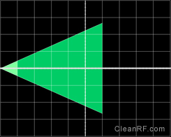
Note 3:Move the focused "dot" to the far left side
of the screen, then while applying voice or data modulation, adjust the Horizontal CH 1 (X) Volts / Div selection control so that the trapezoidal
pattern fills half of the screen horizontally. Adjust Vertical CH 2 (Y) Volts / Div selection control so that the trapezoidal pattern extends
plus / minus two divisions vertically. See "Figure 10a" below.
The Horizontal CH 1(X) input of the oscilloscope will be fed by the model RF-D
(RF Demodulator) via the transmitter; this establishes a pre-amplifier reference signal.
The Vertical CH 2 (Y) input of the oscilloscope will be fed by the series RF-S
(Variable RF Sampler) via the linear amplifier; this establishes a post-amplifier reference signal.
System Self-Diagnostic Test:
With your amplifier turned off or in stand by, transmit voice or data and check to see that
produced is a perfect trapezoidal pattern. This is a self diagnostic test, and you must see a perfect trapezoidal pattern as you are comparing
the original signal to itself. If the trapezoid looks like "Figure 10a" below, then you are ready to turn your amplifier
on and in the operating position to check for its linearity. If you did not produce a perfect trapezoid with the amplifier in the off or
standby position, then you should contact me directly.
Adjustment of voltage scale will be required to achieve resolution - See "Note
3" above
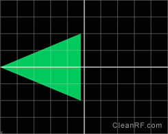
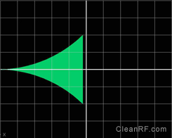
If your amplifier is linear, the oscilloscope pattern will look like a near perfect trapezoid
(Sideways Elongated Triangle) with sharp and distinct angles during voice or data transmissions. See "Figures 10a and 16"
below.
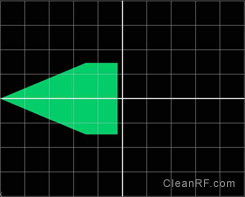
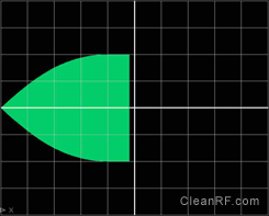
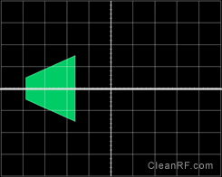
If your amplifier has a linearity issue, the trapezoid's widest end, opposite the point,
will be flattened on the ends, or some other property of the trapezoid will be distorted with a lack of distinct angles.
See "Figures 11, 12 and 13" below.
Click the play button to play.
When palying, double-click video for full screen
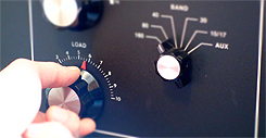
LOAD YOUR AMPLIFIER CORRECLY!
Moreoften than not, a nonlinear trapezoidal pattern is the result of a mistuned
amplifier, particularly with the load control being set with insufficient
loading. To test this, simply advance the load control slightly. With more loading of the amplifier, you will more than likely see the widest
side of the trapezoid edges become nice and crisp as seen in "Figures 10a and 16" above.
If the resulting patterns displayed on the oscilloscope station monitor are well formed, your unintelligible distortion
products will be significantly reduced, resulting in a one to one ratio between your audio frequency and radio frequency bandwidth. This is
a step in the right direction and is more than most hams ever attempt to do in analyzing their on-air signal purity.
Using Your Oscilloscope as an Instantaneous Peak Reading Power Meter:
With a continuous carrier established at the desired power level (measured by and existing
in line watt meter) adjust Vertical CH 2 (Y) Voltage Gain control so your pattern extends plus / minus two divisions vertically.
See “Figures 3 and 10b”.
Now any time your modulated SSB or AM pattern extends to reach the vertical plus / minus
two divisions mark, you will be exactly at the relative power you established with the in line watt meter during the continuous carrier.
See "Figures 4, 8, 10a and 16".